Article
Computational Fluid Dynamics (CFD) For Tensile Membrane Design
Back to listHave you ever wondered how a tensile membrane structure can withstand its surrounding wind forces? Or perhaps how the design of a structure can be obtained in such a way so it is not only lightweight, but also rigid?
Well, design and engineering optimization is the answer to those questions. To achieve such characteristics, we need to find the “sweet spot” between structural rigidity and material efficiency. Hence, design and engineering iterations are crucial for the development of both our ADAS Tensile Membrane or ETFE Skylight systems. During analysis, we apply various types of load to the structural model, and one of the most important load types is identified as wind load.
Why CFD analysis is used
Currently, there are two methods to generate wind load for our Tensile Membrane and ETFE Skylight systems. The first method is by using the standard conventional methods defined in a code of practice. The second is by utilizing the wind load data generated by a Computer Fluid Dynamics (CFD) simulation.
The first method is likely to provide an overestimated wind force since many assumptions have to be made. For simple geometry like cone or barrel structures, this method should be sufficient. However, when it comes to more complex geometry, the CFD method will yield more precise results. With CFD analysis, a designer or an engineer can achieve more geometric freedom.
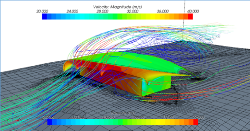
What is CFD analysis?
In a nutshell, CFD is a novel computational approach that can model the behaviour of any kind of fluid, including air. Prior to running a CFD simulation, components such as the 3D model, 3D mesh and boundary condition model have to be set up, along with the simulation preparation. Furthermore, the results have to be post-processed. However drawn-out the process might seem, the rewards are plentiful: one can extract numerous kinds of data from a well set-up model, and wind pressure data is just one of them.
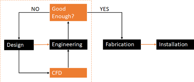
When CFD analysis is carried out
The workflow of our project delivery consists of design, engineering, fabrication, and installation. In between the first two steps, there will be multiple iterations before we proceed to the fabrication process. Between these iterations, CFD analysis does its job in optimising the tensile membrane design.
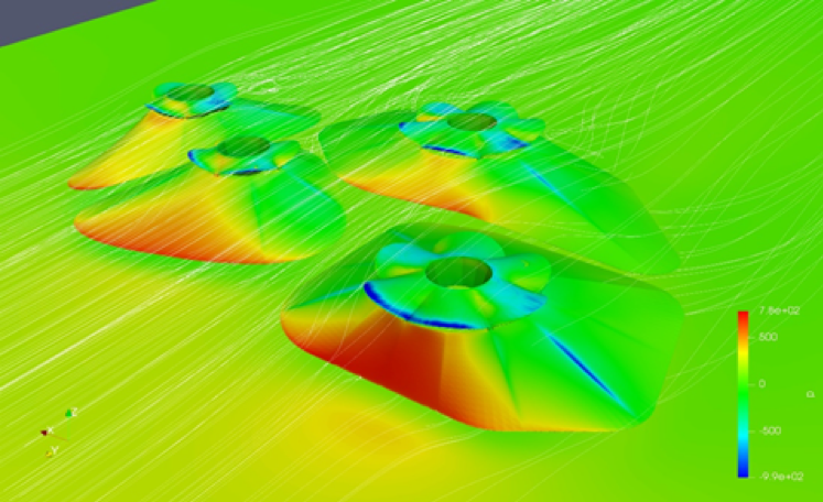
How CFD simulations are utilised
During the engineering stage, the wind load data generated from the CFD simulation will be mapped onto our tensile membrane surface model for calculation. Normally, for each structure, we will simulate several scenarios with different wind directions. This is to ensure that our structure is strong enough to withstand the strength of the wind, and efficient enough in terms of material consumption. Designers can then use the results to modify their structural design. Basically, the more iterations we have, the more ideal the design will be.
All in all, this whole process may look complicated. The repetition of generating results back and forth to rectify a design may sound like quite a journey. Nonetheless, by having our own in-house specialists, this CFD workflow is well-managed. Thus, obtaining an optimum Tensile Membrane or ETFE Skylight design with a lightweight-but-rigid quality is definitely possible.